
6.000 THE LETHAL GAS CHAMBER.
 The
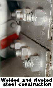
lethal gas chamber is of welded and riveted steel construction. It is hexagonal in shape, but with the corners replaced with the base of an equilateral triangle whose theoretical third angle would have been the original corners of the hexagon. The base of this triangle measures some 7". Thus, each corner is actually two seams instead of one, each seam being one of the base angles of the equilateral triangle. The roof of the chamber is fabricated by a continuation of the side segments at pitch of some 31 degrees from the horizontal. The height of the roof is some 23" above the top of the chamber. The chamber measures some 6' 2" in diameter from corner to corner and some 8' 10" high in the center. The floor area of the chamber is about 29.7 square feet and the volume of the chamber is some 263 cubic feet.
The
lethal gas chamber is of welded and riveted steel construction. It is hexagonal in shape, but with the corners replaced with the base of an equilateral triangle whose theoretical third angle would have been the original corners of the hexagon. The base of this triangle measures some 7". Thus, each corner is actually two seams instead of one, each seam being one of the base angles of the equilateral triangle. The roof of the chamber is fabricated by a continuation of the side segments at pitch of some 31 degrees from the horizontal. The height of the roof is some 23" above the top of the chamber. The chamber measures some 6' 2" in diameter from corner to corner and some 8' 10" high in the center. The floor area of the chamber is about 29.7 square feet and the volume of the chamber is some 263 cubic feet.
 6.001 The lethal chamber has five gasketed windows of bullet proof glass set in riveted steel frames measuring 36" high by 25" wide. The tightness of the window gaskets is controlled by a series of nuts around the window frame which are loosened when the chamber is not being used, to extend the life of the gaskets. Three windows open into the Witness Room and two into the Control Room. The door aperture is 77" high by 34" wide and is oval in shape. A shaped neoprene gasket surrounds the opening which seals against a ribbed clamshell-like door.
Closure of the door and sealing is effected by means of a wormscrew
assembly which is turned by a nautical-type wheel. The wormscrew is threaded
through a curved bar which is fastened on one side to the hinge assembly
and the other to a latching frame (dog). As the worm is turned, it bears
against the curved bar which in turn pulls against the latching dog and
the hinge, thus forcing the door against the gasket and sealing the aperture. The door is hinged in two places on the left side outside the chamber. The intake air valve is mounted at the base of the chamber to the left of the door on the outside. It is piped clockwise around the chamber to
air intake grilles in the facets of the hexagon sides.
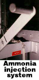 This comprises the air intake manifold system. There is one grille for each side (hexagon facet), except at the location of the door. An ammonia injection system is connected to the air intake manifold to neutralize any gas residue in the chamber and prevent any un-neutralized air-gas mixture from leaking back into the air intake manifold. A shroud completely covers the manifold piping for the intake air.
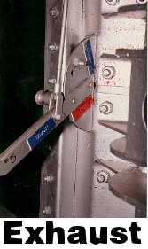 6.002 At the exact center of the top of the lethal gas chamber the exhaust valve and the 7" diameter exhaust piping, exit the chamber and continue on through the exhaust fan and the roof to the exhaust stack. The exhaust stack is some 13.5' above the roof. The Air Exhaust Valve is controlled by a lever and a mechanical connection external to the chamber and to the left of the door. The exhaust fan is coaxial to the exhaust piping above the chamber and is mounted on a frame on the roof of the chamber. The exhaust flue turns 90 degrees at the top of the chamber and enters the exhaust fan where it again turns 90 degrees to exit the building.
There is a mechanical plumbing vent from the gas generator under the
chamber which connects to the exhaust system just prior to the exhaust
fan. This vent passes through the floor of the gas chamber and the roof
of the gas chamber before it inter-connects with the exhaust above the
lethal chamber. The exhaust fan has a back-up motor in the event that the
prime motor fails.
6.003 There are three explosion-proof lighting fixtures mounted in
the ceiling of the chamber spaced at 120 degrees, the first being centered
directly in line with the door. These fixtures are mounted at 90 degrees
to the surface of the ceiling with the inlet being nearest the center of
the chamber. Mounting these at 90 degrees to the surface allows for more
head clearance when standing in the chamber. Additionally, there is an
inlet and an outlet for both a mechanical stethoscope and an electronic
heart monitor.
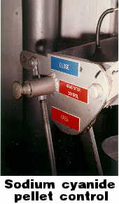 These are to the right of the door as viewed from the outside. There is also mechanical linkage for controlling the sodium cyanide pellet drop into the gas generator and opening the vent valve which enters the right side of the chamber and traverses the floor to center of the chamber. A single chair occupies the center of the chamber directly over the gas generator. This chair is fabricated of steel and has head, arm and leg restraints. The chair is painted with black acid-resistant paint. The chamber interior and exterior has been painted with aluminum acid-resitant paint.
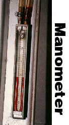 6.004 The lethal gas chamber is also equipped with a manometer, which reads the pressure in the chamber in inches of mercury. This enables the operators to determine if there is a pressure leak in the chamber at any time. There is also a shelf within the chamber upon which is placed a watch glass of phenolphthalein solution which is used as an indicator as to the presence of gas in the chamber. When the chamber is clear of gas, the color of the phenolphthalein turns bright red.
6.005 The Gas Generator and plumbing system occupy the Lethal Gas Chamber, the Control Room, the Chemical Room, and the pit beneath the gas chamber. The Chemical Room contains the start of the system, and the gas generator in/under the lethal gas chamber is the termination of the system which dumps into a special sewer line.
6.006 The Chemical Room contains Acid Mixing Pot (9), trap #1, Ammonia
Injector and Injector Valve (8), Inlet Valve (3), two water spigots at
the Mixing Pot location, and a sink with running water elsewhere in the
room.
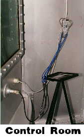
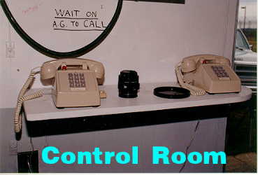
6.007 The Control Room contains Outlet Valve (4), being the only item
not affixed to the lethal chamber. Affixed to the chamber are a Fan Damper
Lever for Air Exhaust Valve (5), Ammonia Injector and Manifold Injector
Valve (7), Air Valve Lever and Air Intake Valve (2), Gas Valve Lever (1),
which controls Gas generator Valve (10), Gas Generator Vent Stack Valve
(A) and Cyanide Briquet Container (B), Packing Gland (11), Manometer (6),
Vent Stack (C), and the Exhaust Fan which has a second back-up motor in
event that the prime motor fails. Additionally, the switches for the emergency exhaust fans for all three rooms (Control, Witness, and Chemical) are located here.
6.008 The Pit beneath the Lethal Chamber contains trap #2, Gas Generator
(D), two drain systems and one water supply system. All piping for the
acid and gas drain and vent system is stainless steel. All piping for the
sink drain and vent system is galvanized. The main drain is 4" black
iron. This drain is not part of the prison's normal sewer system, which
allows the hydrocyanic acid to biodegrade harmlessly into the environment.
6.009 There is an emergency exhaust-fan system to clear all three rooms
in the event of a gas leak and emergency lighting in all three rooms as
well. Further, in the event of a power failure, there is a back-up generating system which will supply electricity to ensure that the exhaust fan does not stop and the vacuum drop in the chamber, causing a leak of lethal gas.
Note: Numbers in parentheses are Eaton's numbers. Letters in parentheses
are the investigator's. Number designations for Valves (numbers 3 and 4)
are transposed in Eaton's text but not in the Eaton drawing. They are correct in all other locations.
6.010 The Gas Generator is comprised of the Gas Generator (D), Gas
Valve Lever (1), the associated actuation linkage and Packing Gland (11),
Gas Valve (10), Gas Generator Vent Stack Valve (A), and Cyanide Briquet
Container (B), Gas Valve (10) is utilized as a seal for testing the integrity (pressure test) of the chamber, as well as, the mechanism for controlling the Cyanide Briquet (pellet) drop, while the actuator additionally controls the opening of the Gas Generator Vent Stack Valve (A). When Gas Valve (10) is closed, the Gas Generator Vent Stack Valve (A) is open, and conversely.
6.011 The two Ammonia Injectors and their associated Injector Valves
(7) and (8) are operated in the following manner: they consist of a glass
bottle filled with ammonia with a rubber stopper. Through two holes in
the rubber stopper, two tubes are inserted. The outlet tube is immersed
in the ammonia (goes deep into the bottle) and is connected to the Injector
Valve, which is in turn, connected to the lethal chamber air-intake manifold
or the piping directly beneath the Acid Mixing Pot (9), before Inlet Valve
(3). The pressurizing tube barely enters the bottle and has a rubber pump
ball on the other end. Air is pumped into the bottle utilizing the rubber
pump ball which creates pressure on the surface of the ammonia, forcing
it out of the outlet tube into the system, when the respective Injector
Valve (7) or (8) is open.